分类: Product Introduction

  • CNC Machine Maintenance Tips That Actually Extend Machine Life

    A cnc machine is one of the most valuable assets on any modern manufacturing floor, and keeping it in peak operating condition is not simply a recommendation — it is a competitive necessity. When a cnc machine runs well, production stays on schedule, tolerances remain tight, and operational costs stay predictable. But when maintenance is neglected, even the most sophisticated equipment can degrade quickly, leading to unplanned downtime, scrapped parts, and costly repairs that could have been avoided entirely.

    This article delivers practical, proven cnc machine maintenance tips that actually work in real industrial environments. Whether you manage a single cnc machine in a job shop or oversee a full fleet of machining centers in a high-volume facility, the principles covered here apply directly. The focus is not on theoretical best practices but on actionable maintenance habits that protect your investment, extend machine life, and support consistent part quality across every production run.

    Understanding Why Consistent Maintenance Matters for a CNC Machine

    The Hidden Cost of Reactive Maintenance

    Many facilities still operate on a reactive maintenance model — fixing problems only after they appear. While this approach may seem cost-efficient in the short term, it consistently proves more expensive over time. A cnc machine that suffers a spindle failure due to inadequate lubrication, for example, may require days or even weeks of downtime, plus significant repair costs. Reactive strategies also make production planning nearly impossible because failures are unpredictable by definition.

    A single unplanned cnc machine failure can ripple across an entire production schedule, delaying customer deliveries and straining operator capacity. The financial impact goes well beyond the repair bill itself. Lost throughput, expedited shipping charges, and damaged customer relationships all accumulate quickly. Proactive maintenance is not just about machine health — it is about protecting business continuity.

    Shifting from reactive to preventive maintenance requires upfront investment in time and process development, but the return is measurable. Facilities that implement structured cnc machine maintenance programs typically report higher machine availability, lower per-part costs, and more stable quality output. The data from your own shop floor will confirm this pattern once a disciplined maintenance schedule is in place.

    How Machine Condition Affects Part Quality

    A well-maintained cnc machine holds tolerances with precision and repeatability. As mechanical components wear — whether due to contaminated coolant, dry guideways, or a misaligned spindle — dimensional accuracy begins to drift. In precision industries such as aerospace, medical device manufacturing, or automotive components, even small deviations can render parts unusable. The relationship between machine condition and output quality is direct and measurable.

    Vibration caused by worn bearings or improperly balanced toolholders can introduce surface finish defects that are difficult to trace back to their source without a systematic inspection process. Operators may notice chatter marks or inconsistent finishes and attribute them to cutting parameters, when the actual root cause is mechanical degradation inside the cnc machine itself. Regular maintenance inspections catch these issues before they become quality problems.

    Maintaining a cnc machine in good mechanical health also means your programming team and operators can trust the machine’s output. When equipment is unreliable, programmers compensate with overly conservative feeds and speeds, reducing productivity unnecessarily. A healthy cnc machine enables the team to run at optimal parameters with confidence, maximizing both throughput and quality simultaneously.

    Daily and Weekly CNC Machine Maintenance Practices

    Start-of-Shift Checks That Prevent Failures

    The most effective cnc machine maintenance habits begin before the first cut is made each shift. A structured pre-shift inspection takes only a few minutes but creates an opportunity to identify developing issues before they cause production problems. Operators should visually inspect the machine for any signs of fluid leaks, unusual residue around the spindle, or debris accumulation in the work envelope. These observations, logged consistently, create a valuable maintenance history.

    Checking coolant levels and concentration is a daily necessity. Coolant that is too dilute loses its lubricating and heat-transfer properties, which accelerates tool wear and can damage the spindle on a cnc machine over time. Checking and maintaining proper coolant concentration with a refractometer is a simple habit with significant consequences when neglected. Coolant should also be inspected for odor and color changes that signal bacterial contamination or tramp oil buildup.

    Air pressure and filter condition should be verified before every shift on any cnc machine that uses pneumatic systems for tool changes, workholding, or chip evacuation. Low or fluctuating air pressure causes erratic tool clamping behavior and can lead to tool pull-out during heavy cuts. Moisture in the air lines is equally damaging. Draining water separators and checking filter condition takes seconds and prevents a category of failures that are frustratingly common in poorly maintained facilities.

    Lubrication Schedules That Protect Critical Components

    Lubrication is the single most impactful maintenance variable for the mechanical longevity of a cnc machine. Linear guideways, ball screws, and bearing systems depend on consistent, correctly specified lubrication to function without excessive wear. Most modern machining centers include automatic lubrication systems, but these systems themselves require periodic inspection to confirm they are functioning and that reservoirs are adequately filled.

    Many operators assume that because a cnc machine has an automatic lubrication system, no manual attention is needed. This is a common and costly misconception. Auto-lube systems can develop blocked lines, failed pump mechanisms, or depleted reservoirs without triggering any alarm on the control panel. A periodic manual check of lube delivery points — looking for actual lubricant presence on guideways and ball screw nuts — confirms the system is working as intended.

    Spindle lubrication and bearing health on a cnc machine require particular attention because spindle repair is among the most expensive service interventions in machine tool maintenance. Following the manufacturer’s spindle warm-up protocol, especially in cooler environments, reduces thermal shock to bearing assemblies. Monitoring spindle noise and vibration patterns over time helps identify bearing wear early, when the repair is still manageable and the spindle can be serviced before a catastrophic failure occurs.

    Mechanical Inspection and Geometric Calibration

    Inspecting Axes, Guideways, and Drive Systems

    Periodic mechanical inspection of a cnc machine goes beyond visual checks and requires physically testing axis movement, backlash, and drive system behavior. Running diagnostic programs that move each axis through its full travel range helps identify binding, irregular motion, or unusual sounds that indicate developing mechanical issues. Many CNC control systems include built-in diagnostic routines specifically designed to assess axis health and servo performance.

    Backlash in ball screws is a normal result of mechanical wear, and it accumulates gradually over the operational life of a cnc machine. Measuring backlash at regular intervals — using a dial indicator against a fixed reference — allows the maintenance team to track wear trends and schedule ball screw replacement at a planned time rather than reacting to a sudden accuracy failure. Most manufacturers publish acceptable backlash tolerances that serve as a useful benchmark for this measurement.

    Guideway surfaces on a cnc machine should be inspected for scoring, pitting, or contamination during scheduled maintenance intervals. Even with automatic lubrication systems in place, metal chips or abrasive particles can occasionally reach guideway surfaces and cause accelerated wear. Cleaning guideways carefully and confirming lubricant film presence during quarterly or semi-annual maintenance visits is a straightforward step that significantly extends the service life of these precision components.

    Geometric Accuracy Checks and Spindle Verification

    Geometric accuracy is the foundation of a cnc machine’s ability to produce dimensionally correct parts. Over time, thermal effects, mechanical wear, and even minor collisions can alter the geometric relationships between machine axes. Performing periodic geometric checks — including squareness of axes, flatness of travel, and spindle runout — with appropriate metrology equipment confirms whether the machine is still within its specified accuracy envelope.

    Spindle runout measurement is particularly important for any cnc machine performing precision boring, reaming, or finish milling operations. Excessive spindle runout directly increases effective tool diameter variation, causing oversize bores and inconsistent surface finishes. A simple test indicator and spindle test bar provide the data needed to determine whether the spindle is within acceptable parameters or requires service attention.

    If a cnc machine has experienced even a minor collision — a tool dragged through a fixture, for example — a geometric verification check should be performed before returning the machine to production. Collisions can shift geometric relationships in ways that are not immediately obvious from visual inspection. Catching geometric errors early, before they produce a batch of out-of-tolerance parts, is the kind of disciplined process that separates professionally managed facilities from reactive shops.

    Electrical, Control, and Software Maintenance

    Keeping Electrical Systems Clean and Reliable

    The electrical systems of a cnc machine are sensitive to dust, humidity, and temperature fluctuations in ways that purely mechanical systems are not. Electrical cabinets on machining centers accumulate fine metallic dust and coolant mist over time, both of which can cause insulation degradation, short circuits, and control failures. Periodic inspection and cleaning of electrical cabinets — with appropriate compressed air or vacuum tools and proper lockout-tagout procedures — should be included in any comprehensive maintenance program.

    Servo drives, VFDs, and control boards on a cnc machine are particularly vulnerable to heat-related failures when cabinet cooling fans become clogged with debris. Checking fan operation and filter condition in control cabinets is a simple task that prevents one of the more common causes of unexpected machine downtime. Replacing cooling filters on the manufacturer’s recommended schedule is inexpensive insurance against heat-related electronics failures.

    Checking cable condition in areas of repeated motion — such as drag chains and pendant cables — is another maintenance task that is easy to overlook until a broken conductor causes an intermittent fault that is difficult to diagnose. Inspecting cable insulation and connector integrity during scheduled maintenance visits catches mechanical fatigue in wiring before it produces a production-interrupting failure on a cnc machine that is in the middle of a critical job.

    Software Backups and Control Parameter Management

    A cnc machine control stores a considerable amount of critical configuration data — machine parameters, tool offset tables, work coordinate systems, and user macros — that represents months or years of setup work. Backing up this data regularly is a maintenance practice that is frequently neglected until a control board failure wipes everything and the recovery process reveals the full cost of not having a recent backup. Most CNC controls support data backup via USB, network connection, or compact flash media.

    Establishing a regular backup schedule — at minimum after any significant parameter change and on a fixed monthly basis — protects a cnc machine’s operational setup data against control hardware failures. Storing backups in at least two separate physical locations, including one off-site or cloud-based option, ensures that a facility fire, flood, or theft event does not compound a hardware failure with a complete data loss.

    Keeping control software and firmware up to date on a cnc machine is also a maintenance consideration that has grown more important as modern machining centers rely increasingly on networked systems and advanced software features. Manufacturer-released firmware updates sometimes address known stability issues or security vulnerabilities. Following a deliberate update process — testing on a non-critical machine first, if possible — keeps control software reliable without introducing new risks into a production environment.

    Building a Sustainable Maintenance Culture Around Your CNC Machine

    Operator Involvement and Ownership

    The most technically sophisticated maintenance program will underperform if the operators who work with the cnc machine every day are not engaged in its care. Operators are in the best position to notice subtle changes in machine behavior — a slight increase in vibration, an unusual sound during tool changes, or a new leak that appeared overnight. Building a culture where operators feel responsible for and empowered to report these observations creates a powerful early warning system.

    Training operators on basic cnc machine maintenance tasks — daily cleaning, coolant checks, chip removal, and pre-shift inspections — distributes the maintenance workload in a practical way and improves machine care consistency. When operators understand how the machine works and why these tasks matter, compliance improves significantly compared to simply handing them a checklist without context. Investing in operator training pays dividends in machine longevity and production reliability.

    Recognizing and rewarding operators who consistently perform good cnc machine care reinforces the cultural expectation that maintenance is everyone’s responsibility. Facilities that treat maintenance as the exclusive domain of a separate maintenance department often find that operators develop a passive relationship with equipment condition. Bridging that gap by involving operators in daily care tasks creates accountability and often surfaces maintenance issues faster than any purely scheduled program could achieve.

    Documentation, Scheduling, and Continuous Improvement

    A maintenance program for a cnc machine without documentation is a maintenance program that cannot be improved. Recording every maintenance action — lubricant added, filters replaced, measurements taken, issues identified and resolved — creates a maintenance history that reveals patterns over time. If a particular component fails repeatedly on a specific machine, the maintenance log provides the evidence needed to investigate root cause and implement a lasting solution.

    Scheduling maintenance activities for a cnc machine proactively — rather than fitting them in opportunistically between jobs — is the difference between a real maintenance program and an informal set of good intentions. Dedicated maintenance windows, whether daily, weekly, monthly, or quarterly, should be treated with the same operational priority as production time. When maintenance is consistently deprioritized in favor of running more parts, the inevitable result is an accelerated accumulation of deferred maintenance that eventually forces a far more disruptive shutdown.

    Using maintenance data from your cnc machine fleet to continuously refine intervals, identify failure trends, and improve inspection procedures is the hallmark of a mature maintenance operation. What works for one machine in one environment may need adjustment in a different facility with different materials, shift patterns, or ambient conditions. Treating the maintenance program itself as a living system that evolves with operational experience ensures that it remains effective rather than becoming a static checklist that gradually loses relevance.

    FAQ

    How often should a CNC machine be fully serviced by a qualified technician?

    Most manufacturers recommend a comprehensive service inspection of a cnc machine at least once per year, with some high-utilization environments requiring semi-annual visits. This full service typically covers geometric accuracy verification, spindle performance testing, drive system calibration, electrical cabinet inspection, and a complete review of all lubrication systems. Following the machine manufacturer’s recommended service intervals is the most reliable starting point, though actual service frequency should be adjusted based on production volume and observed machine condition trends.

    What are the most common causes of unexpected CNC machine downtime?

    Inadequate lubrication, contaminated coolant, neglected chip management, and deferred electrical cabinet maintenance are among the most frequently cited causes of unplanned cnc machine downtime in manufacturing facilities. Spindle bearing failures due to insufficient or incorrect lubrication are particularly costly because spindle repair or replacement is expensive and time-consuming. Establishing daily and weekly maintenance routines that address these specific areas directly reduces the frequency of unplanned stoppages.

    Can operators perform meaningful CNC machine maintenance, or is it always a job for specialists?

    Operators can and should perform a significant portion of routine cnc machine maintenance tasks, including daily cleaning, coolant level and concentration checks, air pressure verification, chip removal, and visual inspection for leaks or unusual conditions. These tasks do not require specialist training but do require clear instruction and consistent follow-through. More complex tasks — such as spindle bearing inspection, geometric calibration, servo parameter adjustment, or electrical fault diagnosis — should be reserved for trained maintenance technicians or qualified service engineers.

    How does coolant management affect long-term CNC machine performance?

    Coolant condition has a direct and significant impact on the long-term performance of a cnc machine. Degraded coolant loses its ability to effectively cool cutting zones and lubricate tool-workpiece interfaces, leading to accelerated tool wear and potential thermal damage to spindle components. Bacterial contamination in coolant systems produces corrosive byproducts that can attack machine surfaces, seals, and guideway coatings over time. Regular coolant concentration measurement, pH testing, and controlled sump cleaning on a defined schedule protect the cnc machine and maintain consistent cutting performance throughout its operational life.

    CTA

    Looking for a reliable CNC machine built for long-term precision, stability, and minimal maintenance?

    Explore DEPU CNC‘s advanced CNC machining solutions designed for aerospace, automotive, mold, medical, and precision manufacturing.
    👉 https://www.depu.com

  • Types of Milling Machine: Complete Guide to Uses and Applications

    A Milling Machine is one of the most versatile and essential tools in modern manufacturing and machining environments. Whether you are setting up a new workshop, upgrading your production line, or simply trying to understand the landscape of metal and material cutting equipment, gaining a solid grasp of what a milling machine does — and how its various types serve different industrial needs — is a critical first step. From small job shops to large-scale aerospace facilities, the milling machine remains a cornerstone of precision fabrication across virtually every sector.

    This guide covers the foundational knowledge every buyer, engineer, or operations manager should have before selecting, specifying, or operating a milling machine. We will break down the core types of milling machines, explore their primary industrial uses, and clarify what distinguishes one configuration from another. By the end of this article, you will have a clear picture of how this category of equipment works, where it applies, and what factors actually matter when evaluating a milling machine for your specific operational context.

    What a Milling Machine Is and How It Works

    The Core Operating Principle

    A milling machine is a power-driven machine tool that uses rotating multi-point cutting tools to remove material from a workpiece. Unlike a lathe, where the workpiece rotates against a stationary cutting tool, a milling machine holds the workpiece stationary on a worktable while the cutter rotates at high speed. This fundamental difference gives the milling machine its characteristic ability to produce complex flat surfaces, slots, gear teeth, threads, and intricate three-dimensional profiles with exceptional accuracy.

    The cutting tool on a milling machine — typically called a mill or end mill — engages the workpiece by moving along one or more axes simultaneously. Most conventional milling machines operate along three linear axes: X (longitudinal), Y (transverse), and Z (vertical). Advanced multi-axis milling machines introduce additional rotational axes, enabling the machining of highly complex geometries in a single setup. The ability to move across multiple axes at once is what makes the milling machine so indispensable for modern precision manufacturing.

    Feed rate, spindle speed, depth of cut, and the type of cutting tool used are the primary variables that operators control on a milling machine. These parameters directly influence surface finish quality, dimensional accuracy, tool life, and material removal rate. Understanding these relationships is essential for anyone responsible for setting up or programming a milling machine in a production environment.

    Key Components Every Operator Should Know

    Every milling machine shares a common set of structural components that define its rigidity, accuracy, and capability. The column and base form the main structural body, providing the rigidity necessary to absorb cutting forces without deflection. The spindle holds and drives the rotating cutting tool, and its precision directly affects the surface quality a milling machine can achieve. The worktable, mounted on the knee or bed, holds the workpiece and moves along the X and Y axes to position material under the cutter.

    The knee on a vertical knee-type milling machine moves vertically to adjust the height of the worktable relative to the spindle. On bed-type milling machines, the table moves only in the horizontal plane while the spindle head adjusts vertically. The arbor, used primarily on horizontal milling machines, is the shaft that holds gang cutters or side milling cutters. Each of these components contributes to the overall performance envelope of the milling machine and must be considered when evaluating a machine for a specific application.

    Major Types of Milling Machines and Their Configurations

    Vertical Milling Machines

    The vertical milling machine is the most widely used configuration in job shops, tool rooms, and general manufacturing environments. In this design, the spindle axis is oriented vertically, meaning the cutter descends from above onto the workpiece lying flat on the worktable. This layout makes it intuitive to set up workpieces, observe the cutting action, and perform a wide range of operations including face milling, end milling, drilling, boring, and slot cutting.

    Within the vertical milling machine category, two common sub-types exist: the turret mill and the bed mill. The turret mill — sometimes called a Bridgeport-style machine — features a stationary spindle with a table that moves in both X and Y, as well as a quill that allows the spindle to move vertically for drilling operations. The bed mill uses a fixed table that moves only along the X axis while the spindle head moves along the Y and Z axes. Bed mills generally offer greater rigidity for heavy-duty cuts, while turret mills offer more flexibility for lighter precision work.

    Vertical milling machines are particularly well-suited for prototype work, mold making, and short-run production jobs where frequent setups and varied geometry are the norm. Their open working area and accessible spindle make them the preferred choice for operators who need maximum visibility and manual control during the machining process.

    Horizontal Milling Machines

    A horizontal milling machine orients its spindle axis horizontally, with cutting tools mounted on an arbor that extends outward from the spindle. This configuration excels at heavy stock removal, particularly when machining wide flat surfaces, slots, and stepped features using gang milling setups — where multiple cutters are mounted simultaneously on the same arbor. The horizontal milling machine generates cutting forces in a direction that is more naturally supported by the machine’s structure, resulting in superior rigidity during aggressive cuts.

    Horizontal milling machines are commonly found in high-volume production environments where the same operation is repeated across large quantities of parts. Industries such as automotive manufacturing, heavy equipment production, and general industrial fabrication rely on horizontal milling machines for consistent, high-throughput material removal. The ability to mount multiple cutters simultaneously significantly reduces cycle times compared to performing the same operations sequentially on a vertical milling machine.

    Universal horizontal milling machines add the ability to swivel the worktable in the horizontal plane, enabling the machining of helical features such as gear teeth and spiral flutes. This added versatility made universal milling machines a staple in gear manufacturing and specialized tool shops for decades, and they remain relevant wherever helical geometry is required.

    CNC Milling Machines

    The computer numerical control (CNC) milling machine represents the most technologically advanced and widely deployed category of milling equipment in modern manufacturing. A CNC milling machine executes machining operations based on pre-programmed instructions, eliminating the need for manual control of each axis movement during cutting. This automation enables the consistent production of complex parts with tight tolerances, often unattainable through manual milling operations.

    CNC milling machines range from 3-axis configurations — which move along X, Y, and Z — to sophisticated 5-axis platforms capable of tilting and rotating the workpiece or spindle head to machine compound angles and undercuts in a single setup. The elimination of multiple setups not only improves cycle time but also eliminates cumulative positioning errors that arise when parts are repositioned between operations. For industries demanding high geometric complexity and part-to-part consistency, the CNC milling machine is the definitive solution.

    Programming a CNC milling machine requires either manual G-code writing or the use of computer-aided manufacturing (CAM) software, which translates 3D CAD models into toolpaths automatically. Modern CAM systems can generate optimized toolpaths that maximize material removal rates while protecting the cutter and maintaining surface quality. The integration of CNC milling machines with automation systems — including robotic part loading, in-process measurement, and automated tool changers — has made fully lights-out manufacturing a practical reality for many high-volume producers.

    Specialized Milling Machine Configurations

    Beyond the three primary categories, several specialized milling machine configurations address niche manufacturing requirements. The planer-type milling machine — also called a plano-miller — is a large-scale machine designed for machining very large workpieces such as machine tool beds, engine blocks, and structural fabrications. These machines feature a wide, long worktable that traverses under fixed or multiple milling heads, enabling the simultaneous processing of large surface areas with high productivity.

    The profile milling machine is designed to produce contoured surfaces by following a master template or executing a digitally defined 3D profile. It is widely used in die and mold manufacturing, aerospace component production, and the fabrication of turbine blades and automotive stamping dies. The thread milling machine, as the name suggests, specializes in producing internal and external threads with a rotating milling cutter rather than a tap or die, offering advantages in thread quality, flexibility, and the ability to machine threads in difficult materials.

    Primary Industrial Uses of a Milling Machine

    Precision Parts Manufacturing

    The milling machine is the backbone of precision parts manufacturing across industries including aerospace, medical devices, electronics, and defense. These sectors demand components with tolerances measured in microns, complex geometric features, and surface finishes that often cannot be achieved through any other machining process. A well-configured milling machine running optimized toolpaths and precision tooling can hold dimensional tolerances of plus or minus a few thousandths of an inch consistently across production batches.

    In aerospace manufacturing, milling machines produce structural aircraft components such as frames, ribs, spars, and fuselage panels from aluminum, titanium, and high-strength alloys. The milling machine’s ability to remove large volumes of material while maintaining precise dimensions makes it the primary machining process for these weight-critical, structurally demanding parts. Medical device manufacturing relies on milling machines to produce implants, surgical instruments, and device housings from stainless steel, cobalt-chrome, and titanium to exacting biocompatibility and dimensional standards.

    Tooling, Die, and Mold Production

    Toolmakers and die shops have long depended on the milling machine as their primary production tool. Injection molds, die casting dies, stamping dies, and forging dies all require the precise machining of hardened steel or pre-hardened tool steel into complex cavity and core geometries. The milling machine — particularly a high-speed 5-axis CNC milling machine — handles the majority of material removal in mold and die production, often followed by grinding and electrical discharge machining for final finishing.

    The economics of tooling production make milling machine efficiency critically important. A single injection mold can represent a capital investment of tens of thousands of dollars, and the time required to mill it out directly impacts project profitability and lead time. Advances in high-speed milling machine technology, combined with superior cutting tool materials such as carbide and ceramic inserts, have dramatically reduced the time required to machine complex mold cavities while improving the surface quality of the finished tool.

    General Fabrication and Job Shop Work

    Job shops and general fabrication facilities depend on the milling machine for the widest variety of tasks. Squaring up bar stock, drilling and boring holes to precise locations, cutting keyways, surfacing castings, and producing one-off custom components are all routine tasks on the shop floor that call for a versatile milling machine. The machine’s ability to handle diverse materials — including steel, aluminum, brass, copper, plastics, and composites — makes it equally at home in a metal shop or a plastics fabrication facility.

    Repair and maintenance machining is another critical use case for the milling machine in industrial environments. When worn or damaged machine components need to be resurfaced, reslotted, or modified to restore function, the milling machine is typically the first piece of equipment reached for. Its combination of precision, versatility, and accessibility makes it irreplaceable in maintenance shops, naval shipyards, mining operations, and anywhere heavy industrial equipment must be kept running.

    Selecting the Right Milling Machine for Your Application

    Evaluating Workpiece Requirements

    The single most important step in selecting a milling machine is a clear analysis of the workpieces you intend to produce. Part size, material, geometric complexity, required tolerances, and expected production volume all directly inform the type, size, and configuration of milling machine that will serve you best. A shop producing large aluminum structural components will have fundamentally different milling machine requirements than one producing small, intricate stainless steel medical components in high volumes.

    Material hardness and machinability are particularly important factors. Milling machines designed for aluminum — which is relatively soft and generates high chip volumes — require high spindle speeds and large chip clearance. Milling machines intended for hardened tool steels or titanium must offer higher torque at lower spindle speeds, superior rigidity, and robust thermal management to handle the extreme cutting forces and heat generation involved. Specifying a milling machine without accounting for material properties is one of the most common and costly mistakes buyers make.

    Automation Level and Production Volume Considerations

    The appropriate level of automation for a milling machine depends heavily on production volume, part complexity, and available skilled labor. For low-volume prototype work or one-off custom parts, a manual or semi-CNC milling machine may offer the most cost-effective and flexible solution. Operators can make real-time adjustments, deal with unexpected material variations, and work through complex setups without the overhead of CNC programming and fixturing.

    For medium to high-volume production, a full CNC milling machine with automatic tool changers, in-process probing, and pallet changers dramatically reduces per-part cycle times and improves consistency. The upfront investment in a CNC milling machine is offset by reduced labor costs, higher throughput, and lower scrap rates over the life of the machine. For the highest volumes, integrating milling machines into automated manufacturing cells — with robotic tending and statistical process control — delivers the lowest cost per part and the highest consistency achievable with current technology.

    FAQ

    What is the main difference between a vertical and horizontal milling machine?

    The primary difference lies in the orientation of the spindle axis. A vertical milling machine has its spindle pointing downward, making it ideal for face milling, end milling, and drilling operations on workpieces lying flat on the table. A horizontal milling machine has its spindle oriented horizontally, which is better suited for heavy stock removal, gang milling operations, and slotting tasks. The choice between the two depends on the type of work being performed, the material involved, and the production volume required.

    Can a milling machine be used for materials other than metal?

    Yes, a milling machine can process a wide range of materials beyond metal, including engineering plastics, composites, wood, foam, and certain ceramics. The cutting tools, spindle speeds, feed rates, and coolant strategies must be adjusted for each material type. Plastics and composites, for example, typically require higher cutting speeds and sharp tooling to avoid melting or delamination, while wood can be milled at very high speeds with specialized router-type cutters. The fundamental operating principle of the milling machine remains the same regardless of the material being cut.

    What does 5-axis mean on a CNC milling machine?

    A 5-axis CNC milling machine can move along five different axes simultaneously: the three standard linear axes (X, Y, Z) plus two additional rotational axes (typically labeled A and B or A and C). This capability allows the milling machine to approach the workpiece from virtually any angle without repositioning, enabling the machining of complex undercuts, compound angles, and sculptured surfaces in a single setup. Five-axis milling machines are widely used in aerospace, mold making, and medical device manufacturing where geometric complexity and setup reduction are critical priorities.

    How often does a milling machine require maintenance?

    Maintenance frequency for a milling machine depends on how intensively it is used, the materials being cut, and the machine’s design. Daily maintenance typically includes cleaning chips from the worktable and guideways, checking and topping up way oil levels, and inspecting cutting tools for wear. Weekly or monthly maintenance may involve checking spindle bearings for play, inspecting ball screws and guideways for wear, verifying axis backlash, and checking coolant concentration. Following the manufacturer’s recommended maintenance schedule is essential to preserving the accuracy, reliability, and service life of any milling machine.

  • What Is a CNC Machine? A Beginner’s Guide

    What Is a CNC Machine? A Beginner’s Guide

    If you are new to modern manufacturing or exploring precision machining for the first time, understanding what a cnc machine is and how it works is an essential starting point. CNC stands for Computer Numerical Control, and it refers to the automated control of machining tools through a computer program. A cnc machine replaces manual operation with pre-programmed digital instructions, enabling consistent, repeatable, and highly precise manufacturing outcomes across a wide range of industries. From aerospace components to custom automotive parts, the cnc machine has become a foundational technology in modern production environments.

    This beginner’s guide is designed to walk you through the core concepts behind a cnc machine, explain its key components, describe how it operates, and help you understand when and why it is used in professional settings. Whether you are a student, a small business owner, or an engineer just getting started, this article will give you a clear and practical foundation. By the end, you will have a solid grasp of what makes a cnc machine such a powerful tool in today’s industrial landscape.

    What Is a CNC Machine and How Does It Work

    The Core Concept of Computer Numerical Control

    A cnc machine operates on a simple but powerful principle: instead of a human manually guiding a cutting or shaping tool, a computer program directs every movement with extreme precision. The instructions fed into the machine are written in a language called G-code, which specifies coordinates, speeds, feed rates, and tool paths. This programming layer is what transforms a raw piece of material into a finished part with consistent accuracy.

    The computer controller reads the G-code and translates it into electrical signals sent to motors and actuators on the machine. These motors move the cutting tool or the workpiece in multiple directions simultaneously, which is why a cnc machine can create highly complex geometries that would be nearly impossible to achieve by hand. The entire process is automated from start to finish once the program is loaded and the material is secured.

    This automated precision is the defining advantage of a cnc machine. Once a program is verified and tested, it can be run thousands of times with virtually identical results. For manufacturers producing high volumes of identical parts, this repeatability is not just convenient — it is essential to quality control and production efficiency.

    The Role of the Operator in CNC Machining

    Although a cnc machine is automated, it still requires skilled human oversight. Operators are responsible for writing or loading the correct program, selecting and installing the right cutting tools, securing the workpiece in place, and monitoring the machine during operation. Any error in setup can lead to scrapped parts or machine damage, so operator knowledge remains critically important.

    More advanced cnc machine environments also involve machinists who understand materials science, tooling geometry, and cutting parameters. They fine-tune programs to optimize cycle times, improve surface finishes, and extend tool life. The human element in CNC machining is not eliminated — it is elevated to a higher level of technical expertise.

    Key Components of a CNC Machine

    The Machine Frame and Axes of Movement

    Every cnc machine is built around a rigid frame that supports all the mechanical and electronic components. The frame must be strong enough to absorb the vibrations and forces generated during cutting without flexing, because any movement in the structure translates directly into inaccuracy in the finished part. High-quality machines use cast iron or welded steel frames specifically engineered for rigidity.

    Movement on a cnc machine is described in terms of axes. A basic machine operates on three axes: X (left-right), Y (front-back), and Z (up-down). More advanced configurations add a fourth or fifth axis, allowing the cutting tool or workpiece to rotate. These multi-axis capabilities dramatically expand what a cnc machine can produce, enabling complex curved surfaces and undercut features in a single setup.

    The precision of axis movement is achieved through servo motors or stepper motors connected to ball screws or linear guides. These components convert rotational motor motion into extremely precise linear or rotational movement of the tool or table. The tighter the tolerances on these mechanical elements, the more accurate the cnc machine will be in practice.

    The Controller Unit and Spindle System

    The controller is the brain of a cnc machine. It houses the computer processor, the human-machine interface (HMI), and all the electronics needed to interpret G-code and coordinate machine movements. Modern controllers offer touchscreen interfaces, real-time monitoring displays, and network connectivity for uploading programs directly from CAD/CAM software.

    The spindle is the component that holds and rotates the cutting tool at high speed. Spindle performance — including its maximum RPM, power output, and runout tolerance — directly affects the quality and speed of machining. A well-maintained spindle on a cnc machine can rotate tools at tens of thousands of revolutions per minute, enabling efficient cutting of metals, plastics, composites, and wood.

    Together, the controller and spindle system define the operational capability of a cnc machine. Upgrading or maintaining these two systems is often the first priority when optimizing an existing machining setup for better performance or expanded capability.

    Common Types of CNC Machines and Their Applications

    CNC Milling Machines

    A CNC milling machine is one of the most versatile types of cnc machine in use today. It uses rotating multi-point cutting tools to remove material from a stationary workpiece. The result can be flat surfaces, contoured profiles, slots, holes, and complex three-dimensional shapes. CNC milling is widely used in aerospace, automotive, medical device, and tooling industries.

    Vertical machining centers (VMCs) and horizontal machining centers (HMCs) are two major categories of CNC milling machines. Vertical machines have the spindle oriented vertically, which makes them well-suited for flat parts and mold cavities. Horizontal machines orient the spindle sideways, which is ideal for heavier workpieces and high-volume production runs. Each type of cnc machine serves different production needs depending on part geometry and throughput requirements.

    CNC Lathes and Turning Centers

    A CNC lathe is a cnc machine designed for producing cylindrical or round parts. The workpiece rotates while a stationary cutting tool removes material from the outside or inside diameter. Common applications include shafts, bushings, pins, fittings, and threaded fasteners. CNC lathes are prevalent in oil and gas, hydraulics, and general precision engineering sectors.

    Modern turning centers combine lathe functionality with milling capability in a single cnc machine. These machines can perform both turning and milling operations in one setup, dramatically reducing cycle times and improving part accuracy by eliminating re-fixturing. For high-volume production of complex rotational parts, a turning center is often the most cost-effective solution available.

    CNC Routers and EDM Machines

    CNC routers are a type of cnc machine optimized for cutting softer materials such as wood, plastics, foam, and composites. They are commonly used in furniture manufacturing, sign-making, and prototype fabrication. While they operate on the same G-code principles as metal-cutting machines, their construction is typically lighter and their spindles are tuned for high-speed, low-force cutting.

    Electrical Discharge Machining (EDM) represents a completely different category of cnc machine. Instead of using a physical cutting tool, EDM removes material through controlled electrical sparks. This process is ideal for hardened tool steels and complex internal geometries that are impossible to reach with conventional cutters. EDM is widely used in mold and die making, where extreme precision and surface finish quality are non-negotiable.

    Getting Started With a CNC Machine as a Beginner

    Understanding G-Code and CAM Software

    For a beginner working with a cnc machine, learning the basics of G-code is an important early step. G-code is the programming language that tells the machine where to move, how fast to move, and what operations to perform. While experienced machinists can write G-code by hand for simple operations, most modern workflows use CAM (Computer-Aided Manufacturing) software to automatically generate G-code from a 3D model.

    CAM software bridges the gap between design and machining. You import a digital model created in CAD software, define the machining operations and tool paths, and the CAM program outputs the G-code file ready for the cnc machine. This workflow significantly lowers the barrier to entry for beginners, as it allows you to focus on learning the machining concepts rather than memorizing syntax.

    Even with CAM software handling code generation, a solid understanding of cutting parameters — such as feed rate, depth of cut, and spindle speed — remains essential. Incorrect parameters can break tools, damage the cnc machine, or produce parts outside tolerance. Most CAM programs provide suggested starting parameters for common materials, which is a helpful starting point for beginners.

    Safety, Maintenance, and First Steps

    Safety is the first priority when operating any cnc machine. Always ensure the machine enclosure is closed before starting a cycle, wear appropriate personal protective equipment, and never reach into the work area while the spindle is rotating. Modern machines include interlock systems that prevent the door from opening during operation, but operator awareness is always the most important safety layer.

    Regular maintenance keeps a cnc machine performing accurately and reliably. This includes lubricating guide rails and ball screws, checking coolant concentration, inspecting tool holders for wear, and cleaning chips from the machine enclosure. A well-maintained machine will hold its tolerances longer and require fewer costly repairs over its service life.

    As a beginner, the most effective way to build competence with a cnc machine is to start with simple parts in easy-to-machine materials like aluminum or soft plastic. Practice setting up work-holding, loading programs, verifying tool offsets, and running the machine in simulation mode before cutting real material. This methodical approach builds confidence and reduces the risk of costly mistakes early on.

    FAQ

    What materials can a CNC machine work with?

    A cnc machine can process a very wide range of materials depending on its type and configuration. Common materials include aluminum, steel, stainless steel, brass, titanium, wood, acrylic, nylon, and composite materials. The key factors that determine material compatibility are spindle power, cutting tool selection, and machine rigidity. Harder materials require more rigid machines and slower cutting parameters, while softer materials can be processed at higher speeds.

    How accurate is a CNC machine compared to manual machining?

    A cnc machine is significantly more accurate than manual machining in most production scenarios. High-quality machines can achieve tolerances of ±0.001 inches (approximately ±0.025 mm) or tighter under ideal conditions. Manual machining accuracy depends heavily on the individual operator’s skill, fatigue level, and technique, making it far less consistent over long production runs. For precision parts requiring tight dimensional control, a cnc machine is the preferred choice.

    Do I need to know how to code to operate a CNC machine?

    You do not need to be a programmer to operate a cnc machine, especially in modern production environments where CAM software generates the G-code automatically. However, a basic familiarity with G-code is highly beneficial. Being able to read and edit simple lines of code helps operators troubleshoot problems, make minor adjustments, and understand what the machine is doing at each step of the process. Many training programs teach G-code fundamentals alongside machine operation skills.

    How long does it take to learn to use a CNC machine effectively?

    The time required to become proficient with a cnc machine varies depending on the complexity of the machine type and the parts being produced. Basic operation and simple part programming can be learned in a matter of weeks with focused training. Developing deep expertise in multi-axis machining, complex programming, tooling selection, and process optimization typically takes one to three years of hands-on experience. Formal apprenticeships and technical school programs provide structured pathways to building this competence efficiently.

     
  • Key Advantages of High-Speed 5-Axis Machining

    Key Advantages of High-Speed 5-Axis Machining

    In the fast-evolving world of modern manufacturing, high-speed 5-axis CNC machining stands out as a transformative technology. It delivers unparalleled efficiency, precision, and versatility for producing complex components. Unlike traditional 3-axis systems limited to linear movements along X, Y, and Z axes, 5-axis machines add two rotary axes, typically A and C or B and C. This enables the cutting tool to approach the workpiece from virtually any direction in a single setup.

    High-speed variants elevate this capability further by incorporating spindles that reach 20,000 to 30,000 RPM or more, combined with advanced drive systems and rigid structures. These machines excel at rapid material removal while maintaining tight tolerances, making them indispensable in industries where time, accuracy, and surface quality are critical.

    Reduced Setup Times

    Traditional 3-axis machining often requires multiple fixturing operations to access different faces of a part. Each repositioning introduces potential errors from misalignment and accumulates tolerances. In contrast, 5-axis machines can machine multiple sides and complex contours in one clamping, minimizing human intervention and improving repeatability.

    Superior Surface Finishes

    With continuous tool orientation adjustment, the cutter maintains optimal contact angles, reducing vibration and tool deflection. This is especially valuable for curved surfaces, impellers, turbine blades, or medical implants where roughness must be minimized without extensive secondary polishing.

    Faster Cycle Times and Higher Productivity

    Shorter, more rigid tools can be used because the machine avoids deep reaches or awkward angles that risk collision in 3-axis setups. Combined with rapid traverse rates and advanced control systems featuring RTCP (Rotational Tool Center Point) functionality, these machines achieve aggressive feeds while preserving accuracy. Material removal rates increase dramatically, lowering per-part costs and shortening lead times.

    Enhanced Tool Life

    Better angles distribute cutting forces more evenly, reduce heat buildup, and prevent chatter. This is crucial when working with expensive or difficult-to-machine materials like titanium, Inconel, or high-strength alloys common in aerospace and energy sectors.

    Complex Geometry Capability

    Engineers can create organic shapes, undercuts, and intricate features that would be impossible or prohibitively expensive with fewer axes. This supports part consolidation, replacing multi-piece assemblies with single monolithic components, improving strength and reducing weight.

    Introducing DEPU G630

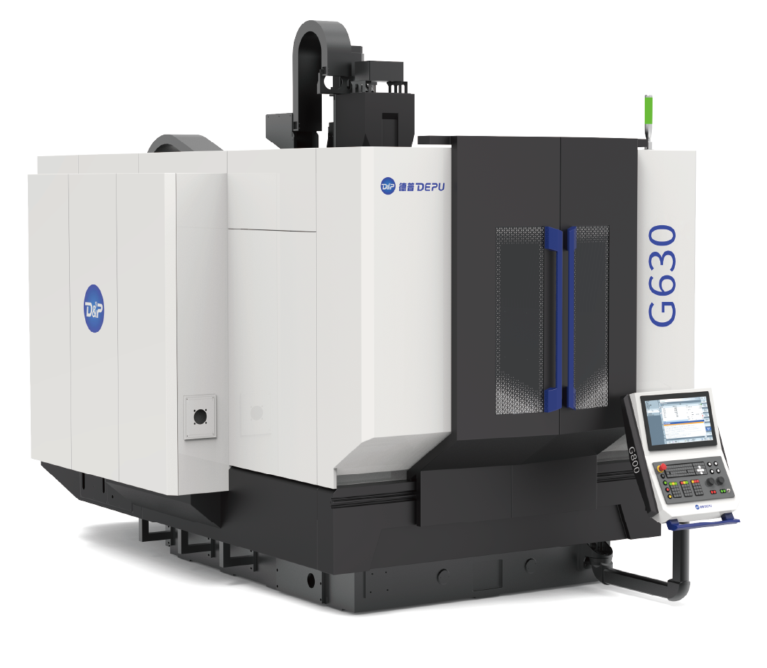
    A strong example of high-speed 5-axis engineering is the DEPU G630 High-Speed 5-Axis CNC Milling Machine. Built on a robust gantry-type structure with high-quality HT300 cast iron components, the G630 combines rigidity and dynamic performance for precision work.

    Key specifications highlight its capabilities:

    • Travel: 650/650/500 mm (X/Y/Z)
    • Table: Ø630 mm with max workpiece dimensions of Ф700×400 mm and 850 kg load capacity
    • Rotary Axes: A-axis +30° to -130°, C-axis 360°
    • Spindle: HSK-E63 interface, up to 24,000 rpm, 40 kW power, and significant torque (72/94 N·m S1/S6)
    • Rapid Traverses: 45 m/min on linear axes, with fast rotary speeds
    • Tool Magazine: 40 tools standard, supporting larger diameters and weights

    The machine features a dual-supported cradle rotary table with direct-drive motors and Heidenhain feedback for lasting precision. Dual-ball-screw Y-axis drive enhances dynamics, while full closed-loop control with high-resolution encoders ensures accuracy. A high-performance spindle cooling system maintains thermal stability.

    Design emphasizes operator comfort and productivity: double-opening doors for easy access, large viewing windows, overhead loading capability, and fully enclosed guards with an overhead cover to manage oil mist. Standard Siemens CNC with RTCP, optional probing systems, tool setters, and advanced chip management make the G630 a complete solution for high-mix, high-precision production.

    The G630 targets automotive, mechanical engineering, and aerospace users needing precision molds and complex components. Its finite element-optimized design, precision roller guides, and ball screws deliver the stability required for sustained high-speed operation without sacrificing accuracy.

    Conclusion

    As Industry 4.0 advances, high-speed 5-axis machines increasingly integrate with automation, real-time monitoring, and AI-driven optimization. Features like thermal compensation, adaptive control, and seamless CAD/CAM integration further boost uptime and consistency.

    Investment in such technology yields strong returns through reduced labor, lower tooling costs, faster throughput, and superior part quality. For manufacturers facing skilled labor shortages and growing demand for customization, high-speed 5-axis machining is a competitive necessity.

    In conclusion, high-speed 5-axis CNC technology, exemplified by advanced systems like the DEPU G630, empowers manufacturers to push the boundaries of what is possible. By combining multi-axis flexibility with rapid, precise cutting, these machines drive efficiency, innovation, and excellence across global industries. As material and design requirements grow more demanding, high-speed 5-axis solutions will continue to shape the future of precision manufacturing.

  • Simultaneous 5-Axis Machining in Precision Manufacturing

    Simultaneous 5-Axis Machining in Precision Manufacturing

    Simultaneous 5-Axis Machining in Precision Manufacturing

    Simultaneous 5-axis machining represents the pinnacle of CNC technology, enabling the cutting tool and workpiece to move concurrently along five axes, three linear (X, Y, Z) and two rotational (typically A and C or B and C). This continuous, synchronized motion allows the tool to maintain optimal orientation relative to the workpiece surface throughout the entire operation, unlike 3+2 positional machining where rotary axes are locked during cutting.

    In simultaneous 5-axis operations, the machine executes complex toolpaths where all axes interpolate smoothly. Advanced CNC controls with features like RTCP (Rotational Tool Center Point) and sophisticated kinematics compensation ensure precise coordination, compensating for mechanical dynamics and thermal effects in real time. This capability transforms how manufacturers approach intricate geometries, delivering superior results in efficiency, accuracy, and surface quality.

    Core Advantages

    The most significant benefit is single-setup machining of complex parts. Traditional 3-axis or even 4-axis processes often require multiple fixturing operations to access different faces or angles. Each repositioning introduces alignment errors, accumulates tolerances, and increases labor time. Simultaneous 5-axis eliminates most of these setups, allowing nearly the entire surface of a part, including undercuts, compound curves, and organic shapes, to be machined in one clamping. This dramatically reduces cycle times and improves repeatability.

    Superior surface finishes emerge naturally from continuous tool engagement. By keeping the cutter at the ideal angle, often using the side of the tool rather than just the tip, vibration decreases, tool deflection minimizes, and scallop heights reduce. Parts often exit the machine with finishes that require little to no secondary polishing, saving time and cost while enhancing fatigue resistance in critical components.

    Enhanced tool life and cutting performance follow from shorter, more rigid tooling. The machine can tilt and rotate to avoid collisions or deep reaches, permitting aggressive parameters without chatter. Heat dissipation improves, and cutting forces distribute more evenly, extending insert or end mill longevity, especially when processing tough materials like titanium, Inconel, or hardened steels.

    Greater design freedom empowers engineers. Simultaneous 5-axis supports part consolidation, where multi-piece assemblies become monolithic components. This reduces weight, improves structural integrity, and lowers assembly costs, advantages highly valued in weight-sensitive industries.

    Accuracy also benefits from fewer setups. Feature-to-feature relationships remain tighter because the part stays fixed in the same coordinate system throughout machining. Modern machines with high-resolution encoders, direct-drive rotary tables, and thermal compensation deliver consistent micron-level precision even during long runs.

    Key Applications

    Simultaneous 5-axis machining excels in sectors demanding high complexity and tight tolerances. Aerospace manufacturers use it for turbine blades, impellers, structural brackets, and engine casings. The technology handles swept surfaces and thin walls while maintaining aerodynamic profiles and balancing requirements.

    In medical device production, it creates custom implants, prosthetics, and surgical instruments from biocompatible materials. Organic, patient-specific geometries require the smooth, continuous motion that only simultaneous 5-axis can reliably deliver.

    Automotive and mold & die industries leverage the speed for complex tooling, conformal cooling channels, and high-performance engine components. Energy and defense sectors apply it to precision rotors, housings, and specialized prototypes.

    DEPU Reliable Simultaneous 5-Axis Performance

    Leading manufacturers turn to advanced solutions like those from DEPU, a specialist in high-end 5-axis CNC machining centers. Established in 2021 with a core team boasting over 20 years of machine tool R&D experience, DEPU serves Fortune 500 companies with precision-focused equipment and comprehensive manufacturing support.

    The G630 High-Speed 5-Axis Machining Center exemplifies DEPU’s commitment to simultaneous machining excellence. Built on a rigid gantry structure using high-quality HT300 cast iron, the G630 features a dual-supported cradle rotary table with direct-drive motors and Heidenhain feedback systems. Its A-axis (+30° to -130°) and C-axis (360°) enable full simultaneous contouring, while the 24,000 rpm HSK-E63 spindle (40 kW, significant torque) supports high-efficiency roughing and finishing in one setup.

    With travels of 650/650/500 mm, a Ø630 mm table (850 kg load capacity), rapid traverses up to 45 m/min, and standard Siemens CNC with RTCP, the G630 delivers the dynamic response and precision needed for demanding simultaneous operations. Features such as dual-ball-screw Y-axis drive, precision roller guides, full closed-loop control with 10 nm resolution encoders, and advanced spindle cooling ensure thermal stability and lasting accuracy during continuous multi-axis motion.

    Operator-friendly design includes double-opening doors, large viewing windows, and effective chip and mist management. Optional probing, tool setting, and automation integrations further enhance productivity for high-mix production. DEPU’s G Series, including models like the G300 and G800, targets automotive, aerospace, and mechanical engineering applications requiring precision molds and complex components.

    As Industry 4.0 progresses, simultaneous 5-axis machines integrate with automation, real-time monitoring, and AI optimization. Hybrid additive-subtractive processes and digital twins further expand possibilities.

    For manufacturers seeking competitive edges in quality, speed, and innovation, simultaneous 5-axis technology is indispensable. Solutions from forward-thinking fifth axis CNC providers like DEPU make this advanced capability accessible and reliable, driving the next generation of precision components across global industries.

  • How the DEPU G Series Gantry Machine Structure Sustains Long-Term 5-Axis Machining Precision

    How the DEPU G Series Gantry Machine Structure Sustains Long-Term 5-Axis Machining Precision

    Introduction: The Problem With Precision That Doesn’t Last

    In precision manufacturing, a machine that hits tolerance on day one but drifts within six months is not a precision machine — it is a liability. For manufacturers in aerospace, automotive, medical device, and mold-making industries, long-term dimensional consistency is as critical as initial accuracy.

    The structural choices made during machine design determine whether precision is a launch-day specification or a sustained production reality. Symmetry, material quality, heat management, and drivetrain stiffness all compound over time — either in favor of accuracy or against it.

    The DEPU G Series cradle 5-axis machining center was engineered specifically to address this challenge. Its gantry-type symmetrical structure, high-quality cast iron construction, and full closed-loop control architecture are not marketing features — they are engineering decisions made to ensure that the machine performing on month one is the same machine performing on year three.

    1. Gantry Machine Structure: Symmetry as a Precision Strategy

    The most fundamental structural decision in the DEPU G Series is its gantry-type symmetrical layout. Unlike C-frame designs where the column offsets the load path asymmetrically, a gantry structure distributes cutting forces evenly across both sides of the machine body.

    This symmetry delivers three measurable precision benefits:

    • Balanced deformation under load — Symmetric force paths mean that deflection under cutting loads is predictable and consistent, rather than directionally biased
    • Reduced thermal asymmetry — Symmetrical structures expand more evenly when temperature changes, minimizing the positional drift that asymmetric designs generate under thermal cycling
    • Higher natural frequency — The closed-frame gantry geometry raises the machine’s resonant frequency, reducing susceptibility to vibration-induced surface errors during aggressive cutting

    For the DEPU G Series, this structural symmetry is combined with main castings made from high-quality cast iron that has been double heat-treated to eliminate residual stress — a process that prevents the slow dimensional changes that untreated castings undergo in service.

    2. CNC Machine Rigidity: Cast Iron, Finite Element Optimization, and Stiff Drivetrains

    Structural rigidity in the DEPU G Series cradle 5-axis machining center is not achieved through mass alone — it is the result of systematic engineering across the machine’s entire load path.

    Key rigidity design decisions include:

    • High-quality cast iron throughout all major structural components — Cast iron’s superior vibration damping coefficient compared to fabricated steel structures reduces chatter and improves surface finish under dynamic cutting conditions
    • Finite element optimization of all moving components — Every structural member has been analyzed and refined to maximize stiffness-to-weight ratio, lightening moving masses while preserving the rigidity needed for accurate positioning
    • NSK/THK precision ball screws and Schneeberger/THK linear guide rails — Full-series standard drivetrain components from top-tier suppliers ensure that the mechanical transmission system contributes no measurable backlash or compliance to the positioning loop

    Together, these choices give the G Series the CNC machine rigidity needed to maintain 5-axis machining accuracy of 0.003–0.006 mm across the full working envelope — from the compact G300 to the large-format G800.

    3. Thermal Stability: Double Heat Treatment and Active Cooling

    Thermal stability is one of the most demanding requirements in high precision machining. Steel expands approximately 10–12 microns per meter per degree Celsius — meaning that even a modest temperature rise in a machine’s column or spindle housing can shift a part’s dimensions beyond tolerance without any mechanical fault.

    The DEPU G Series manages thermal stability through a two-layer approach:

    • Structural thermal preparation — All major cast components undergo double heat treatment before machining. This process relieves the residual stresses introduced during casting, which would otherwise cause slow dimensional changes as the machine is used and temperature cycles
    • Active thermal management in operation — A standard water chiller continuously cools the spindle assembly, preventing heat buildup from transferring into the machine’s structural members during production. Cabinet air conditioning stabilizes the electrical and control environment, eliminating thermally induced servo drift

    For manufacturers running multi-hour production cycles — particularly on aerospace components with tight geometric tolerances — this combination of passive structural preparation and active thermal management ensures that part dimensions at the end of a shift match those at the beginning.

    4. DD Rotary Table: Direct Drive Precision Without Mechanical Transmission Loss

    The cradle rotary table is the defining structural element of the DEPU G Series architecture, and its design has a direct impact on 5-axis machining accuracy.

    The G Series standard DD (direct drive) rotary table delivers rotary axis precision through:

    • YRT rotary table bearings — Designed specifically for rotary table applications, YRT bearings provide high axial and radial load capacity with minimal runout, maintaining angular accuracy under heavy workpiece loads
    • Elimination of mechanical transmission — Unlike worm-gear driven tables, a DD table has no gear mesh error, no backlash, and no transmission compliance — the motor directly drives the table without intermediate mechanical elements that can wear or flex
    • Heidenhain angular position feedback — Real-time angular measurement by Heidenhain’s position feedback system closes the rotary axis loop, continuously correcting for any deviation between commanded and actual angular position

    For the DEPU G Series cradle 5-axis machining center, this rotary axis architecture delivers A/C-axis positioning accuracy of 8 arcseconds and repeat positioning accuracy of 4 arcseconds — specifications that are maintained in production rather than only at acceptance testing.

    5. Full Closed-Loop Control: Heidenhain Feedback Across All Axes

    Structural and mechanical precision set the foundation, but full closed-loop control is what ensures that the machine’s positioning accuracy is verified and corrected in real time during every cutting cycle.

    The DEPU G Series implements closed-loop control through:

    • Linear encoders on all X/Y/Z axes (standard from G630 and G800) — Direct position measurement at the point of interest — rather than at the motor — eliminates the accumulated errors of ball screw thermal expansion, wear, and elastic deformation from the positioning loop
    • Heidenhain position feedback on the DD rotary table — Angular errors on the A and C axes are measured and corrected in real time, preventing the rotary axis drift that degrades complex surface accuracy over extended runs
    • Servo tool magazine — Consistent tool change positioning ensures that tool-length offsets remain repeatable between operations, eliminating a common source of dimensional variation in multi-tool programs

    This full closed-loop architecture means that the G Series does not just achieve precision — it actively maintains precision, compensating for the thermal, mechanical, and dynamic disturbances that accumulate during real production conditions.

    6. Application Range: Where G Series Structural Precision Delivers ROI

    The structural design choices of the DEPU G Series cradle 5-axis machining center translate into measurable production advantages across a range of demanding industries:

    • Aerospace — Turbine blades, structural brackets, and engine housings require sustained geometric accuracy across long production runs. The G Series’s rigidity and closed-loop rotary control deliver the consistent airfoil tolerances and datum repeatability these parts demand
    • Automotive — Precision molds and dies require high surface finish quality combined with tight form accuracy. The G Series’s gantry rigidity and vibration damping characteristics support aggressive material removal without compromising final surface quality
    • Medical devices — Implant components and surgical instruments require micron-level dimensional consistency. The G Series’s thermal stability and DD table precision maintain the tolerances needed for regulatory compliance across full production batches
    • Precision mold-making — Complex cavity geometries require sustained accuracy over long machining cycles. The G Series’s structural thermal preparation and active cooling prevent the mid-cycle drift that causes mismatch between mold halves

    With three platform sizes — G300 (workpiece up to Φ390×250mm), G630 (up to Φ700×400mm), and G800 (up to Φ900×500mm) — the G Series covers the full range of precision cradle 5-axis applications from compact medical components to large aerospace assemblies.

    Conclusion: Precision That Holds

    The DEPU G Series cradle 5-axis machining center demonstrates that sustained machining precision is an engineering outcome, not a specification claim. Through gantry symmetry, double heat-treated cast iron construction, direct-drive rotary technology, and Heidenhain closed-loop feedback across all axes, the G Series is designed to deliver the same accuracy on year three that it delivers on day one.

    For manufacturers where long-term dimensional consistency directly determines product quality, yield rates, and customer confidence, the structural investment in the DEPU G Series is an investment in reliable, repeatable, production-grade precision.

    FAQ

    1. What makes the gantry structure of the DEPU G Series effective for long-term precision? The gantry’s symmetrical design distributes cutting forces and thermal expansion evenly across both sides of the machine body, preventing the asymmetric deformation and positional drift that C-frame machines experience under load and temperature cycling. Combined with double heat-treated cast iron castings, the structure maintains its geometric accuracy over years of production use.

    2. Why does the DEPU G Series use a DD rotary table instead of a conventional worm-gear table? A direct-drive DD table eliminates the gear mesh error, backlash, and transmission compliance inherent in worm-gear designs. With YRT rotary bearings and Heidenhain angular feedback, the DD table delivers rotary axis positioning accuracy of 8 arcseconds with no mechanical wear mechanism that could degrade accuracy over time.

    3. How does double heat treatment of castings contribute to machining accuracy? Casting processes introduce residual stresses into the material. Without treatment, these stresses slowly relax in service, causing gradual dimensional changes in the machine structure. Double heat treatment fully relieves these stresses before machining, ensuring that the structural geometry established during manufacturing remains stable throughout the machine’s operational life.

    4. What is the difference between the G300, G630, and G800 in terms of precision capability? All three models share the same gantry structure design principles, DD rotary table, and closed-loop control architecture. The primary differences are workpiece capacity (Φ390mm to Φ900mm), table load (50 kg to 1,200 kg), and available tool magazine sizes (24T to 60T). Positioning accuracy is 0.003 mm on the G300 and 0.006 mm on the G630 and G800.

    5. Which industries benefit most from the DEPU G Series cradle 5-axis machining center? Aerospace (turbine blades, structural parts), automotive (precision molds and dies), medical devices (implants, surgical instruments), and precision mold-making all benefit significantly. These industries share a common requirement: dimensional accuracy that holds across full production batches, not just at machine acceptance.

  • How the DEPU U Series Machine Structure Delivers Micron-Level Machining Accuracy in 5-Axis Operations

    How the DEPU U Series Machine Structure Delivers Micron-Level Machining Accuracy in 5-Axis Operations

    How the DEPU U Series Machine Structure Delivers Micron-Level Machining Accuracy in 5-Axis Operations

    Introduction: Why Machine Structure Is the Precision Ceiling

    In modern precision manufacturing, achieving micron-level machining accuracy is no longer a competitive advantage — it is a baseline requirement. Aerospace brackets, medical implants, automotive molds, and marine structural components all demand tolerances that leave no room for structural compromise.

    Yet across the industry, many manufacturers overlook a fundamental truth: no matter how advanced the CNC control system or how optimized the toolpath, the machine structure itself defines the upper limit of achievable precision. Spindle speed and software intelligence cannot compensate for a chassis that flexes under load or drifts with temperature change.

    The DEPU U Series 5-axis machining center was engineered from the ground up with this principle at its core. As a vertical and horizontal conversion 5-axis platform, it combines structural rigor with intelligent configuration to deliver consistent, repeatable accuracy across demanding production environments.

    1. CNC Machine Rigidity: The Foundation of Stable Multi-Axis Cutting

    Achieving micron-level machining accuracy begins with a structure that resists deformation — not just under static load, but under the dynamic forces of high-speed 5-axis cutting.

    The DEPU U Series addresses this through several structural decisions:

    • Wall-type machine body with T-shaped base structure — The integral column and large cross-section contact surfaces give the frame exceptionally high rigidity, minimizing flex during aggressive cutting passes
    • Full-stroke X-axis slide support — Unlike partial-support designs, the X-axis slide maintains contact along its entire travel, eliminating cantilever-induced deflection
    • Y-axis three-rail structure — The triple-guideway Y-axis delivers higher response speed and superior vibration damping compared to dual-rail alternatives

    This level of CNC machine rigidity ensures that the tool position remains stable even during complex simultaneous 5-axis movements — a prerequisite for maintaining positional accuracy below 0.006 mm across the full working envelope.

    2. Thermal Stability CNC: Controlling Drift at the Micron Scale

    Thermal variation is one of the most underestimated precision killers in high-volume machining. Steel expands approximately 10–12 microns per meter per degree Celsius. On a machine with 1,000 mm of X-axis travel, even a 1°C ambient shift can introduce dimensional errors that exceed tolerance limits for critical components.

    The DEPU U Series manages thermal stability CNC through:

    • Integrated water cooling system (standard) — Active cooling of the spindle and key structural zones reduces heat buildup during continuous operation
    • Symmetrical structural design — Balanced load paths minimize asymmetric thermal expansion that causes positional drift
    • Cabinet air conditioning (standard) — Stabilizes the electrical and control environment, preventing thermally induced servo errors

    For manufacturers running long production cycles — particularly in aerospace and medical applications where batch consistency is critical — these thermal control measures are what separate repeatable micron-level results from intermittent ones.

    3. Dynamic Stability: Managing Vibration in High-Speed 5-Axis Operations

    Dynamic stability becomes the decisive factor when cutting speeds increase or when machining thin-walled components where chatter causes surface damage and dimensional deviation.

    The DEPU U Series 5-axis machining center addresses dynamic stability through:

    • High-precision ball screw and roller rail system (full series standard) — NSK/THK-grade components deliver the stiffness needed to maintain accurate positioning under dynamic cutting loads
    • B-axis large rail span with heavy-duty turntable bearings — Completely independently designed and manufactured, the B-axis provides long service life and high load-bearing capacity with minimal backlash
    • Moving mass optimization — All components are finite-element optimized to reduce inertia on moving assemblies, improving response and reducing resonance

    The result is smoother surface finishes, extended tool life, and the ability to machine difficult materials — titanium, high-strength alloys, and hardened steels — without sacrificing positional accuracy.

    4. Full Closed-Loop Control: Heidenhain Feedback Across All Axes

    Machine structure provides the physical foundation, but full closed-loop control is what translates structural capability into sustained measurement accuracy.

    The DEPU U Series 5-axis machining center is equipped with:

    • Encoder / linear scale (standard) — Position feedback on all linear axes eliminates the accumulated error that open-loop systems cannot detect or correct
    • DD rotary table with Heidenhain position feedback — The direct-drive turntable operates without mechanical transmission losses, and Heidenhain’s angular feedback maintains rotary accuracy across extended production runs
    • Servo tool magazine — Precise tool change positioning ensures consistent tool-length offset repeatability, preventing measurement variation between operations

    This closed-loop architecture is particularly critical in 5-axis machining, where positioning errors on rotary axes amplify into surface errors on complex workpiece geometries. For the DEPU U Series, full closed-loop control across all five axes ensures that X/Y/Z positioning accuracy of 0.006–0.012 mm is not just a specification — it is a sustained production reality.

    5. Vertical and Horizontal Conversion: Structural Design for Full-Surface Access

    One of the most distinctive structural features of the DEPU U Series 5-axis machining center is its vertical-horizontal conversion swivel head — a design that eliminates a fundamental limitation of conventional 5-axis platforms.

    In vertical machining mode, the spindle center can traverse the entire table surface without generating tool join errors. This is made possible by:

    • C-axis: 360° continuous rotation — Full rotational freedom without mechanical interference
    • A-axis: -30° to +180° swivel range — Wide angular coverage for undercut features and complex approach angles
    • T-shaped base with integral column — Provides the structural stability needed to maintain accuracy when the head operates in horizontal orientation, where gravitational loading changes significantly

    For aerospace structural parts, large marine components, and precision molds requiring five-sided machining in a single setup, this conversion capability — backed by rigid structural support — is what enables the elimination of datum shifts and the cumulative positioning errors that multi-setup workflows inevitably introduce.

    6. Long-Term Precision: Built for Production, Not Just Demonstration

    True high precision machining reliability must be measured not at installation, but after months and years of continuous production use. Structural fatigue, thermal cycling, and environmental exposure all degrade machine accuracy over time if not accounted for in the original design.

    The DEPU U Series ensures long-term stability through:

    • Precision-grade linear components throughout — Full-series standard ball screws and roller rails from NSK/THK maintain specification-grade performance over extended service life
    • Chiller system (standard) — Continuous spindle cooling prevents the thermal fatigue that degrades bearing preload and spindle runout accuracy over time
    • Lubrication system (standard) — Automated lubrication of all guideway and screw interfaces prevents wear-induced backlash and maintains positioning repeatability

    For manufacturers evaluating total cost of ownership, these built-in reliability features translate directly into lower maintenance frequency, fewer recalibration cycles, and consistent machining quality throughout the machine’s operational life.

    Conclusion: Structure Is What Sustains Precision

    Software, control systems, and toolpath optimization all contribute to machining performance. But for the DEPU U Series 5-axis machining center, precision begins at the structural level — with a machine body designed to resist deformation, manage heat, absorb vibration, and maintain accuracy across every axis, every cycle, and every year of production.

    For manufacturers in aerospace, automotive, marine, and medical device industries who require consistent micron-level machining accuracy, the structural foundation of the DEPU U Series is not a feature — it is the capability itself.

    FAQ

    1. Why is machine structure critical for micron-level machining accuracy in 5-axis operations? Machine structure directly determines rigidity, thermal stability, and vibration control — the three physical factors that define whether micron-level accuracy can be achieved and sustained across production runs. Even advanced control systems cannot compensate for structural deformation or thermal drift.

    2. How does the DEPU U Series achieve CNC machine rigidity across its full working range? The U Series uses a wall-type machine body with a T-shaped base, an integral column, and a full-stroke X-axis slide support. Combined with a Y-axis three-rail structure, these design choices maintain structural stiffness across the complete travel envelope, not just at the center of the working zone.

    3. What makes the vertical and horizontal conversion design of the U Series structurally significant? The swivel head’s wide A-axis range (-30° to +180°) combined with 360° C-axis rotation allows the spindle to access all five faces of a workpiece in a single setup. The T-shaped base provides the structural counterbalance needed to maintain positional accuracy when the head operates in horizontal orientation, where load distribution changes substantially.

    4. How does full closed-loop control contribute to sustained precision in the DEPU U Series? Heidenhain-based position feedback on all linear and rotary axes continuously corrects for any deviation between commanded and actual position. This eliminates the accumulated error typical of open-loop or semi-closed-loop systems, ensuring that positioning accuracy of 0.006–0.012 mm is maintained across extended production cycles rather than only at the start of a shift.

    5. What industries benefit most from the DEPU U Series machine structure design? Aerospace (structural parts, brackets, engine components), marine (large structural assemblies), automotive (precision molds and dies), and medical device manufacturing all benefit from the U Series’s combination of high load capacity (up to 8,000 kg), wide table range (1,000–2,500 mm), and sustained micron-level accuracy.

  • Common CNC Machining Mistakes That Lead to Poor Tolerance and How to Avoid Them

    Machine Calibration and Environmental Factors Affecting CNC Machining Tolerance

    Spindle runout, axis misalignment, and backlash causing systematic dimensional drift

    When a machine’s spindle doesn’t rotate perfectly around its center axis, it makes cutting tools less accurate. This problem usually starts with improper machine setup, which causes linear guides to drift off their intended path as they move. The result? Parts end up with distorted shapes that don’t meet specifications. Another common issue comes from backlash in ball screw systems. These tiny delays happen every time the machine changes direction, and over time these small errors can add up to more than 0.1 millimeters across an entire production batch. If factories ignore these problems, studies show quality control failures go up by roughly 30 percent according to recent research published in engineering journals. To keep things running smoothly, most shops now rely on laser alignment checks combined with regular maintenance routines. This helps ensure consistent results down to about 5 microns of precision, which is critical for high tolerance manufacturing applications.

    Thermal expansion and ambient temperature fluctuations undermining CNC machining accuracy

    Temperature changes cause some serious problems when it comes to keeping things dimensionally accurate, but they’re often overlooked in manufacturing settings. Steel structures and aluminum components tend to grow about 12 micrometers per meter for every degree Celsius increase. That means if a workshop experiences typical temperature swings of around 10 degrees during the day, a 400 millimeter component could end up shifting by as much as 0.05 mm – which is way beyond what’s acceptable for aerospace specifications. The heat expansion of spindle bearings alone contributes roughly 40 percent to positioning mistakes in precision manufacturing operations. Smart factories tackle these issues by maintaining stable environments within plus or minus one degree Celsius and implementing specialized software solutions. These programs adjust cutting paths based on live sensor readings taken from key areas of the machinery, helping compensate for those pesky thermal variations that creep into production processes.

    Tool-Related Errors That Compromise CNC Machining Precision

    Worn, improperly selected, or unbalanced cutting tools introducing tolerance deviations

    When tool wear goes unchecked, it accounts for roughly 25 to 30 percent of all machining problems according to research from Machining Science and Technology. Operators often overlook how dull cutting edges create uneven chip removal and hot spots on the workpiece, which can push dimensional tolerances past the critical ±0.05 mm range when working with hardened steels. Finishing operations using coarse grain carbide tools tend to generate unwanted vibrations that actually damage surface quality rather than improve it. The problem gets worse with unbalanced cutting tools. At high RPM speeds, centrifugal force starts pushing against both the tool itself and whatever part is being machined. This becomes particularly problematic during thin wall machining or when reaching into deep cavities where stability matters most.

    Cutter compensation errors and tool deflection during high-load CNC milling operations

    The way tools bend increases dramatically as the overhang gets longer, which really matters during those deep pocket cuts or complex contours. Take a standard 10 mm carbide end mill sticking out 50 mm for example. Under around 200 Newtons of force, this setup might actually flex by about 15 microns. That small amount of movement can lead to roughly 0.1 mm differences in the final shape when working with tough materials like titanium. Many computer-aided manufacturing programs still struggle to accurately predict these forces because they don’t account properly for the actual angles where the cutting happens. This leads to bigger problems down the line as mistakes build upon each other. To keep things within acceptable tolerances, shops need to invest in systems that monitor loads while cutting and plan paths based on machine rigidity rather than relying solely on old fashioned offset charts.

    Workholding Instability and Fixture-Induced Errors in CNC Machining

    Soft jaw inaccuracies, chip buildup, and clamping-induced part distortion

    Unstable workholding continues to be one of the main causes of scrap that could have been avoided. When soft jaws are made without considering how they’ll actually fit the finished part, there’s already misalignment right from the start. Chips building up between fixtures and parts create all sorts of problems too, since they make support inconsistent and allow tiny shifts during machining cycles. What really hurts quality though? Too much clamping pressure on delicate parts like thin walls or anything not very stiff. These parts get squished during machining, then spring back slightly once released, resulting in dimensions that don’t meet specs even if everything else went perfectly. According to research published last year in Machining Science & Technology, these fixture issues cause around 15% of all preventable dimensional scrap in high precision manufacturing environments. To combat this problem, shops need to regularly remachine jaws using master reference parts as guides, install systems that automatically clear chips away during operations, and invest in hydraulic clamps that can adjust pressure based on real time feedback.

    Programming, Setup, and Process Parameter Mistakes in CNC Machining

    G-code Logic Flaws, Incorrect Tool Offsets, and Coordinate System Misalignment

    Even a tiny mistake like a misplaced decimal point or failing to verify the coordinate system can push features off by plus or minus 0.005 inches, which often means scrapping what should have been a good part. When tool length or diameter offsets go wrong, the whole toolpath gets misaligned compared to what was programmed in the first place, leading to errors as big as 0.2 mm if nobody catches them early. Getting the Work Coordinate System right matters just as much. An incorrect Z-zero setting creates problems that spread through every operation after that. Most shops swear by touch probe checks and running full simulations before cutting into actual materials these days. According to industry reports, around 37 percent of all scrapped parts come down to missing steps during pre-production checks. That’s why smart manufacturers stick to standard checklists, have two people double check those offset settings, and run dry runs without any workpiece loaded whenever possible.

    Suboptimal Speed, Feed, and Depth-of-Cut Settings Amplifying Vibration and Surface Deviation

    The way we set our cutting parameters really affects how stable things stay during machining, how much heat builds up, and ultimately how long our tools last before needing replacement. When spindle speeds get too high, they start exciting those resonant frequencies that can cause tools to deflect anywhere from 50 to 100 microns – not good for anyone wanting tight tolerances. On the flip side, if feed rates aren’t sufficient enough, especially when working with tough materials like stainless steel or nickel alloys, we end up with work hardening issues. This leads to faster tool wear and surfaces that are roughly 30% rougher than desired. Getting depth of cut right matters too. Go too deep and we get chatter problems; go too shallow and it becomes rubbing instead of proper cutting action, neither of which gives us that nice smooth finish everyone wants. Finding optimal settings depends heavily on what material we’re dealing with and the part geometry. For instance, titanium generally needs about 30% slower speeds compared to aluminum just to keep thermal distortion under control. Most shops now rely on sensor systems that monitor vibrations in real time so operators can tweak parameters as needed. And let’s face it, nobody disputes that looking at chips coming off the workpiece tells us volumes about whether everything is running smoothly or if something needs adjusting.

    FAQ Section

    What is spindle runout and how does it affect CNC machining?

    Spindle runout is when the machine’s spindle does not rotate perfectly around its center axis, leading to inaccuracies in cutting tools and resulting in distorted parts that do not meet specifications.

    How do ambient temperature fluctuations affect CNC machining accuracy?

    Temperature changes cause materials like steel and aluminum to expand or contract, leading to dimensional inaccuracies in machined parts. This can be problematic in precision applications such as aerospace manufacturing.

    Why is tool wear a significant issue in CNC machining?

    Unchecked tool wear leads to uneven chip removal and hot spots, causing dimensional inaccuracies and quality issues, which can account for 25 to 30 percent of machining problems.

    How can workholding instability cause errors in CNC machining?

    Unstable workholding, such as soft jaw inaccuracies and chip buildup, leads to misalignment and shifts during machining, resulting in parts that do not meet specifications.

    What role does programming play in CNC machining errors?

    Programming errors, such as incorrect tool offsets and coordinate system misalignment, can lead to significant dimensional deviations and scrap parts if not caught early.

  • 5 Axis CNC vs. 3 Axis CNC: Key Differences You Should Know

    Introduction: Why Axis Configuration Matters in Modern Manufacturing

    In CNC machining, the number of controlled axes directly determines what geometries can be produced, how accurately they can be manufactured, and how efficiently production can scale. When comparing 5 axis CNC vs. 3 axis CNC, the difference is not incremental—it fundamentally reshapes machining strategy, part quality, and total manufacturing cost.

    While 3 axis CNC machining remains widely used for simple prismatic parts, 5 axis CNC machining has become critical for aerospace, medical, energy, and high-precision industrial applications where complex geometries, tight tolerances, and advanced materials are non-negotiable.

    This article explains the key differences you should know, from motion capability and accuracy to cost justification and real-world use cases.

    What Is 3 Axis CNC Machining?

    3 axis CNC machining operates along three linear axes: X, Y, and Z. The cutting tool approaches the workpiece from a single direction, requiring multiple setups if features exist on different faces.

    Characteristics of 3 Axis CNC Machining

    • Linear movement only (X, Y, Z)

    • Multiple fixtures required for multi-face parts

    • Higher risk of cumulative alignment error

    • Lower machine and programming cost

    3 axis CNC machining is effective for flat surfaces, slots, holes, and basic housings. However, once geometry becomes contoured or multi-angled, its limitations become apparent.

    What Is 5 Axis CNC Machining?

    5 axis CNC machining adds two rotational axes (typically A and B or A and C) to the traditional three linear axes. This allows either the tool or the workpiece to tilt and rotate during cutting.

    Core Capabilities of 5 Axis CNC Machining

    • Simultaneous machining from multiple angles

    • Single-setup manufacturing for complex parts

    • Shorter tool lengths and better rigidity

    • Continuous toolpath control

    By enabling access to complex geometries in one setup, 5 axis CNC machining dramatically improves accuracy, surface finish, and production efficiency.

    5 Axis CNC vs. 3 Axis CNC: Side-by-Side Comparison

    Parameter 3 Axis CNC 5 Axis CNC
    Axis Movement X, Y, Z X, Y, Z + 2 rotary axes
    Setup Count Multiple Single (in most cases)
    Geometric Complexity Limited Extremely high
    Typical Tolerance ±0.005″ ±0.0005″
    Surface Finish 1.6–3.2 µm Ra <0.4 µm Ra
    Tool Reach Long tools required Short, rigid tools
    Programming Complexity Low High
    Application Scope General machining Aerospace, medical, advanced parts

    This comparison highlights why 5 axis CNC machining is increasingly favored for complex parts manufacturing.

    Accuracy and Tolerance: The Precision Gap

    In high-stakes industries, tolerance stack-up from multiple setups is unacceptable. With 3 axis CNC machining, every re-fixturing introduces potential misalignment.

    5 axis CNC machining eliminates this risk by maintaining datum integrity throughout the process. Continuous multi-axis tool control enables:

    • Micron-level geometric consistency

    • Improved positional accuracy

    • Superior repeatability across production batches

    For aerospace brackets, turbine components, and orthopedic implants, this precision is not optional—it is mandatory.

    Surface Finish and Tool Engagement

    Surface quality is directly affected by tool angle and engagement consistency.

    • 3 axis CNC machining often requires secondary finishing operations

    • 5 axis CNC machining maintains optimal tool orientation throughout the cut

    As a result, 5 axis CNC machining achieves surface finishes below 0.4 µm Ra, reducing polishing time and improving fatigue resistance in load-bearing parts.

    Efficiency, Lead Time, and Cost Considerations

    When 3 Axis CNC Makes Sense

    • Simple geometries

    • Low-volume or prototype work

    • Cost-sensitive projects with loose tolerances

    When 5 Axis CNC Is Worth the Investment

    • Complex parts manufacturing

    • Tight tolerances and high surface requirements

    • Advanced materials like titanium and Inconel

    • Reduced lead time through single-setup machining

    Although 5 axis CNC machines have higher upfront costs, total cost of ownership is often lower due to reduced setups, fewer fixtures, and lower scrap rates.

    Industry Applications: Where the Difference Matters Most

    Aerospace Manufacturing

    5 axis CNC machining enables lightweight structural components, impellers, and turbine blades that are impossible to machine accurately on 3 axis systems.

    Medical Device Manufacturing

    Custom implants and surgical tools require smooth surfaces and complex organic shapes—ideal for 5 axis CNC machining.

    Energy and Industrial Equipment

    High-load components benefit from precise geometry and superior surface integrity delivered by 5 axis CNC machining.

    Choosing Between 5 Axis CNC and 3 Axis CNC

    The decision should be driven by part geometry, tolerance requirements, and long-term production strategy—not machine cost alone.

    If your parts involve:

    • Multiple compound angles

    • Tight GD&T requirements

    • High-performance materials

    Then 5 axis CNC machining is the correct technical choice.

    FAQ

    1. Is 5 axis CNC machining more accurate than 3 axis CNC machining?

    Yes. 5 axis CNC machining reduces setup error and maintains consistent datums, resulting in significantly higher accuracy.

    2. Why is 5 axis CNC machining critical for complex parts manufacturing?

    It allows multi-face and contoured features to be machined in a single setup, improving precision and efficiency.

    3. Is 3 axis CNC machining becoming obsolete?

    No. 3 axis CNC machining remains effective for simple parts, but it cannot replace 5 axis CNC machining for complex geometries.

    4. Does 5 axis CNC machining reduce production time?

    Yes. Fewer setups, shorter tools, and optimized toolpaths significantly reduce total machining time.

  • The Role of Advanced Quality Control (CMM & Laser Calibration) in Precision CNC Parts

    Why Dimensional Accuracy Is Non-Negotiable for Precision CNC Parts

    GD&T as the Language of Functionality: Translating Design Intent to Real-World Performance

    GD&T, or Geometric Dimensioning and Tolerancing, acts as the common language engineers use to communicate how parts should actually work when manufactured through precision CNC processes. Regular dimensional measurements only tell part of the story. With GD&T symbols, we’re not just talking about sizes anymore but how components need to fit together, move relative to each other, and maintain proper interaction throughout their lifecycle. Take flatness specifications for example they stop those annoying wobbles in mounting plates. Perpendicularity requirements keep things square where they need to be. And position tolerances? They ensure those hole patterns line up perfectly with what they connect to. When done right, these controls save manufacturers from serious headaches down the road. Think about it: no more fluid leaks coming out of hydraulic systems because surfaces aren’t aligned properly. No vibrations tearing apart aerospace connections due to misalignment issues. Medical devices last longer without wearing out prematurely thanks to better tolerances. According to standards set by ASME Y14.5, GD&T goes beyond mere shapes and dimensions. It’s really about capturing exactly how a part needs to function in its intended application.

    Tolerance Drift Costs: How QC Failures Impact Scrap Rate, Rework, and First-Pass Yield

    When parts don’t meet specifications, it creates a chain reaction of problems for manufacturers. Just a tiny 0.05mm flatness issue often means going back to the drawing board for remachining, which basically doubles what we spend on labor, tools, and factory space. Think about this: in factories making thousands of units every month, a mere 2% scrap rate translates to losing around $60,000 worth of raw materials each month. Industry data tells us that when tolerances shift beyond 10 microns, first pass yields drop by about 18% on average. And if thermal expansion isn’t controlled properly in aluminum parts, rework rates jump up 34%. The numbers get really scary when looking at quality control failures. According to the Ponemon Institute (2023), serious QC issues cost manufacturers approximately $740,000 per year, and this number keeps climbing by about 11% annually. Beyond just the money lost on materials, these issues lead to shipment delays, increased warranty claims, and ultimately damage to relationships with customers who expect consistent quality.

    CMM Inspection: The Gold Standard for Verifying Precision CNC Parts

    For checking dimensional accuracy in precision CNC parts, Coordinate Measuring Machines (CMMs) are still considered the gold standard by most manufacturers. These machines work through either tactile probes or optical scanners to map out intricate shapes and then check against CAD designs, spotting differences as small as a single micron. The importance of this becomes really apparent in industries such as aerospace and medical devices. A tiny measurement error here could mean disaster on the ground or inside someone’s body. That’s why these fields face intense oversight from standards like ISO 9001 and AS9100, which demand rock solid quality control at every stage of production.

    Touch-Probe vs. Optical CMMs: Trade-offs in Speed, Resolution, and Suitability for High-Mix CNC Production

    Touch probe CMMs can achieve really good accuracy around plus or minus 0.9 microns when measuring things like bearing seats and other flat surfaces but there’s a catch. They take measurements one point at a time which means they’re not so great when speed matters. On the flip side, optical CMM systems that work with lasers or structured light scan whole surfaces almost instantly. This makes them perfect for checking complex shapes and delicate thin walled components during initial production runs. But watch out for tricky materials. These optical systems often have trouble with shiny surfaces, see through materials, or those dark matte finishes that absorb all the light. For shops dealing with lots of different parts and frequent setup changes, combining both technologies works best. Start with optical scanning to spot any obvious issues across the whole component, then follow up with targeted touch probing on those specific areas controlled by GD&T tolerances. This two pronged approach typically saves about two thirds of the time compared to relying solely on traditional probing methods, while still maintaining reliable quality assurance throughout manufacturing.

    Laser Calibration: Ensuring CNC Machine Tool Accuracy Before Cutting Begins

    Most CNC machines experience some degree of drift over time because of things like heat changes, parts wearing down, and vibrations throughout the structure these problems build up even before any actual cutting happens. Laser calibration tools actually measure all those tiny geometry issues right at the start of production. They check for straight line errors, how much the machine tilts or turns (pitch, yaw, roll), and whether different axes are properly aligned across the entire workspace. Traditional ballbar tests just look at circular movements, but modern volumetric calibration goes further by tracking how multiple axes interact while simulating actual cutting operations. What this shows are tricky nonlinear errors such as when spindles drift in complex 5-axis setups, position shifts caused by metal expansion (sometimes around 0.05mm in steel when temperatures swing ±15 degrees Celsius), or when axes aren’t perfectly perpendicular to each other. When manufacturers create custom compensation charts based on these findings, they can push positioning accuracy below 5 microns which stops dimensional problems before they ever reach the finished product.

    API XD-Laser and FrogScan™ Flash Peel 3: Validating Volumetric Accuracy in Multi-Axis CNC Systems

    Tools such as the API XD-Laser and FrogScan Flash Peel 3 allow for thorough calibration of multi-axis CNC machines in ways that go beyond basic checks. These devices don’t take measurements one after another like traditional methods do. Instead, they work while the machine is actually moving through its normal operations, tracking things like how vibrations and structural bending impact accuracy when parts are being machined. What gets measured includes things like how straight the machine moves at different speeds, whether rotating parts stay stable, if axes remain properly aligned in three dimensions, and how the machine handles sudden changes in direction. The big difference here is that these tools catch errors that happen during actual operation rather than just sitting still. This leads to creating compensation models that get built right into the CNC control system itself. What happens next? Machines become much more reliable and precise over time. Manufacturers see fewer scrapped parts because potential problems with geometry get spotted early on, before any cutting even starts.

    Closing the Loop: Real-Time In-Process Measurement for Precision CNC Parts

    When manufacturers implement real time measurements during production, they shift quality control from something done after the fact to something that happens while making precision CNC parts. Putting sensors like laser scanners or fast touch probes right into the machining process lets them spot when dimensions start drifting off track. This can happen because machines heat up, tools gradually wear down, or materials just aren’t perfectly uniform. The system then automatically adjusts the cutting path mid cycle, keeping tolerances really tight around ±0.005 mm most of the time. Factory stats show these systems cut down on wasted material by about 35% and boost initial success rates since problems get caught before finishing touches. There are still hurdles to overcome though, especially dealing with all that sensor data coming in fast and figuring out how to separate useful signals from background noise. But the payoff is worth it: faster production runs, fewer delays caused by fixing mistakes later, and better proof that products meet those tough specs required for critical components.

    FAQ

    What is GD&T?

    GD&T, or Geometric Dimensioning and Tolerancing, is a system used by engineers to communicate precise information about the shape, size, and allowable deviation of parts to ensure they function correctly in their intended applications.

    Why is dimensional accuracy important in CNC machining?

    Dimensional accuracy is crucial as it affects the performance, reliability, and lifetime of the manufactured parts. Poor accuracy can lead to increased scrap rates, rework costs, and product failures.

    What role do CMMs play in precision CNC machining?

    CMMs, or Coordinate Measuring Machines, are used to verify dimensional accuracy by comparing the manufactured parts’ geometry against the CAD designs, ensuring that any deviations are within acceptable limits.

    What’s the difference between touch-probe and optical CMMs?

    Touch-probe CMMs measure one point at a time, providing high accuracy but at a slower pace. Optical CMMs use lasers or light to scan entire surfaces quickly but may struggle with reflective or transparent materials.

    How does laser calibration improve CNC machine accuracy?

    Laser calibration identifies geometric inaccuracies in CNC machines, allowing manufacturers to address issues before cutting begins, leading to greater accuracy and fewer dimensional problems in the final products.